
Высшего профессионального образования «Чувашский государственный университет имени И. Н. Ульянова» английский язык тексты для чтения и перевода чебоксары 2010
| Вид материала | Документы |
СодержаниеThe CPU Main Components Input Output Environment |
- Становление и развитие системы инженерно-технического образования в чувашской республике, 448.7kb.
- Социально-педагогические условия повышения качества вузовского педагогического образования, 532.62kb.
- Труд рабочей молодежи в промышленности марийской, мордовской и чувашской республик:, 705.63kb.
- Правовое регулирование частных и публичных отношений при поставке товаров для государственных, 367.89kb.
- Федеральное агенство по образованию министерство образования и науки российской федерации, 332kb.
- Генезис и динамика поэтики марийского рассказа в контексте литератур народов поволжья, 1207.02kb.
- Перечень вступительных испытаний в фгбоу впо чувашский государственный университет, 172.51kb.
- Рабочая программа кандидатского минимума по дисциплине «иностранный язык» (английский, 122.2kb.
- Исторические и типологические формы, 761.45kb.
- Формирование культуры самоорганизации учебно-познавательной деятельности курсантов, 464.46kb.
The CPU Main Components
As it is known the two functional units of the CPU are the control unit (CU) and the arithmetic-logical unit (ALU). The control unit manages and coordinates the entire computer system. It obtains instructions from the program stored in main memory, interprets the instructions, and issues signals that cause other units of the system to execute them.
The control unit operates by reading one instruction at a time from memory and taking the action called for by each instruction. In this way it controls the flow between the main storage and the arithmetic-logical unit.
The control unit has the following components: a counter that selects the instructions, one at a time, from memory; a register that temporarily holds the instructions read from memory while it is being executed; a decoder that takes the coded instruction and breaks it down into individual commands necessary to carry it out; a clock, which produces marks at regular intervals. These timing marks are electronic and very rapid.
The sequence of control unit operations is as follows. The next instruction to be executed is read out from primary storage into the storage register. The instruction is passed from the storage register to the instruction register. Then the operation part of the instruction is decoded so that the proper arithmetic or logical operation can be performed. The address of the operand is sent from the instruction register to the address register. At last the instruction counter register provides the address register with the address of the next instruction to be executed.
The arithmetic-logical unit (ALU) executes the processing operations called for by the instructions brought from main memory by the control unit. Binary arithmetic, the logical operations and some special functions are performed by the arithmetical-logical unit. .
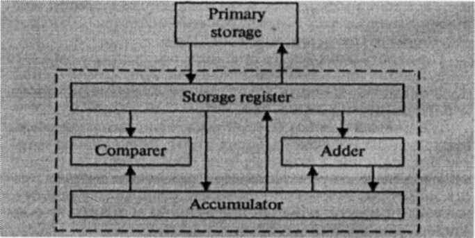
Data enter the ALU and return to main storage through the storage register. The accumulator serving as a register holds the results of processing operations. The results of arithmetic operations are returned to the accumulator for transfer to main storage through the storage register. The comparer performs logical comparisons of the contents of the storage register and the accumulator. Typically, the comparer tests for conditions such as "less than", "equal to", or "greater than".
So as you see the primary components of the arithmetic-logical unit are banks of
bitable devices, which are called registers. Their purpose is to hold the numbers involved in the calculation and hold the results temporarily until they can be transferred to memory. At the core of the ALU is a very high-speed binary adder, which is used to carry out at least the four basic arithmetic functions (addition, subtraction, multiplication and division). The logical unit consists of electronic circuitry which compares information and makes decisions based upon the results of the comparison.
Input Output Environment
Data and instructions must enter the data processing system, and information must leave it. These operations are performed by input and output (I/O) units that link the computer to its external environment.
The I/O environment may be human-related or human-independent. A remote banking terminal is an example of a human-related input environment, and a printer is an example of a device that produces output in a human-readable format. An example of a human-independent input environment is a device that measures traffic flow. A reel of magnetic tape upon which the collected data are stored in binary format is an example of a human-independent output.
Input-Output Interfaces. Data enter input units in forms that depend upon the particular device used. For example, data are entered from a keyboard in a manner similar to typing, and this differs from the way that data are entered by a bar-code scanner. However, regardless of the forms in which they receive their inputs, all input devices must provide a computer with data that are transformed into the binary codes that the primary memory of the computer is designed to accept. This transformation is accomplished by units called I/O interfaces. Input interfaces are designed to match the unique physical or electrical characteristics of input devices to the requirements of the computer system. Similarly, when output is available, output interfaces must be designed to reverse the process and to adapt the output to the external environment. These I/O interfaces are also called channels or input-output processors (IOP). The major differences between devices are the media that they use and the speed with which they are able to transfer data to or from primary storage.
Input-Output Device Speed. Input-output devices can be classified as high-speed, medium-speed, and low-speed. The devices are grouped according to their speed. It should be noted that the high-speed devices are entirely electronic in their operation or magnetic media that can be moved at high speed. Those high-speed devices are both input and output devices and are used as secondary storage. The low-speed devices are those with complex mechanical motion or operate at the speed of a human operator. The medium-speed devices are those that fall between — they tend to have mechanical moving parts which are more complex than the high-speed devices but not as complex as the low-speed.
High-speed devices: magnetic disk; magnetic tape. Medium-speed devices: card readers; line printers; page printers; computer output microfilms; magnetic diskette; optical character readers; optical mark readers; visual displays.
Low-speed devices: bar-code readers; character printers; digitizers; keyboard input devices; plotters; voice recognition and response units.