
Short-Circuit Calculations
| Вид материала | Документы |
СодержаниеThree Winding Transformers Type of Motor Type of Generator Minimum Available Current Maximum Available Current |
- Схемотехническое моделирование аналоговых устройств (Circuit simulation of analog devices), 37.87kb.
- Ўзбекистон республикаси соғЛИҚни сақлаш вазирлигининг буйру, 865.78kb.
- Short escape to barcelona-madrid, 14.88kb.
- Целостности ферментных систем, 40.61kb.
- Лабораторной экспресс-диагностики или stat-анализа (stat- short-Turn-Around Time) неотложных, 87.46kb.
- Thomas Nagel «What Does It All Mean? A very Short Introduction to Philosophy», 865.31kb.
- «язвенная болезнь в практике врача-эндоскописта», 232.24kb.
- Издано Всемирной Организацией Здравоохранения в 2001, 2108.63kb.
- Программа кратчайшего пути на орграфе Program Short; {Кратчайшие пути на графе, 81.9kb.
- Задачи: Классификация моделей, отражающих последствия кредитно-денежной политики Определить, 43.29kb.
Short-Circuit Calculations
A Handbook to Accompany the
Short-Circuit Calculation Program
From MSHA’s Approval and Certification Center
By Wayne L. Carey
January 4, 2006
Short-Circuit Calculations
Introduction
One of the jobs of the Mine Safety and Health Administration’s (MSHA’s) Approval and Certification Center (A&CC) is to approve electrical equipment for underground mines. An important part of this job is to determine if circuit protective devices are sized and set correctly. Sizing of circuit protective devices can only be done when maximum available short-circuit current is known. Setting of the devices can only be done when minimum available short-circuit current is known. The A&CC has a computer program available through the MSHA website (msha.gov) to calculate available short-circuit currents in mine power systems. This program, other programs, or hand calculation can be used to perform short-circuit calculations. Any method used requires specific data on the mine power system. All this data is converted to resistance and reactance values for each component in the system. Impedance can then be calculated and then minimum and maximum available currents. This paper describes the data needed for each type of circuit component and how to obtain the data. It also describes methods used by the computer program to calculate available short-circuit currents.
Utility
The first step in analyzing a power system is to get the data for the power available at the site, the utility data. This data can be obtained from the power company. When calling the power company, explain the type of information you need and ask for the engineering department. It may be helpful to explain why you need the information.
The power company will be able to supply this information for the point in the power system where their responsibility for the power system ends and the customer’s responsibility starts. A common location for this point is the secondary of a pole or pad mounted transformer. If the customer is responsible for the transformer, the transition point would be the primary of the transformer. Sometimes a pole mounted disconnect will be the transition point. The power company will specify where in the system their responsibility ends.
The data needed is the line to line voltage (VLL), short-circuit kVA (kVASC), and X/R. Obtaining the voltage is simple enough. Short-circuit kVA is the power available at a bolted three phase fault. Bolted means all three phases connected together with no added impedance. X/R is the ratio of reactance to resistance in the supply. Short-circuit kVA and X/R may need to be derived from other data.
Short-circuit current (ISC) is sometimes supplied by the power company rather than short-circuit kVA. This current is the current in one phase of a three phase bolted fault. The short-circuit kVA can be calculated from the short-circuit current using the following equation.
 (Eq. 1)
If you’re not doing these calculations every day, it is sometimes hard to remember when to include the square root of three factor. Power in a three phase circuit is three times the single phase power or three times the current in one phase times the line to neutral voltage (VLN). The line to neutral voltage is the line to line voltage divided by the square root of three.
 (Eq. 2)
Power factor (PF) is sometimes specified instead of X/R. This must be the short-circuit power factor. Power factor is defined as the cosine of the angle between voltage and current. X/R is the tangent of this same angle. X/R can be found from power factor by taking the tangent of the inverse cosine of the power factor.
 (Eq. 3)
When neither X/R nor power factor are specified for the utility, it is usually safe to assume the impedance of the utility is all reactance and X/R is infinite. Unless there are many miles of transmission line, the impedance of the utility will be mainly reactance in the generator. This is all the data needed for the utility. From this data, the short-circuit calculation program can be used to calculate impedance (Z), resistance (R), and reactance (X). This data can also be calculated manually.
Impedance is calculated from VLL and short-circuit kVA.
 (Eq. 4)
Resistance and reactance are then calculated from the impedance using X/R.
Since:
 (Eq. 5)
 (Eq. 5a) And
  (Eq. 5b)
Resistance and reactance are calculated at the voltages for the points in the circuit where the short-circuit currents are calculated. For example, even though the utility voltage may be 69 kilovolts (kV), if the short-circuit currents are being calculated further down the circuit where the voltage is 2400 volts, the resistance and reactance will be calculated at 2400 volts. The computer program initially calculates resistance and reactance for the utility at the utility voltage. As the program works down through a circuit, encountering transformers, it converts the resistance and reactance to the new voltage by multiplying by the ratio of the voltages squared.
 (Eq. 6)
Where: R2 = resistance at secondary voltage
R1 = resistance at primary voltage
V2 = secondary voltage
V1 = primary voltage
This formula is the result of conservation of energy. Energy into the transformer (V12/R1) equals energy out of the transformer (V22/R2).
Transformers
Transformers are specified by output voltage (V), kVA rating, percent impedance (%Z), and X/R ratio. The X/R ratio is the ratio of reactance to resistance. This information, with the exception of X/R, is usually on the transformer nameplate. If X/R is not specified on the nameplate, the transformer manufacturer may be able to supply this. When contacting the transformer manufacturer, it may be helpful to have the transformer serial number. If X/R cannot be obtained, a value of 4.9 is typical and can be used in calculations. Impedance (Z) is calculated from V, kVA, and %Z.
 Or
Or  (Eq. 7)
Resistance and reactance are then calculated from Z and X/R as they were for the utility. Again, these resistances and reactances are for a short-circuit at the secondary of the transformer. If the short-circuit is at a point further down the circuit and after another transformer, the voltage at the short-circuit should be used in equation 7. Alternatively, the calculated resistances and reactances can be converted to the new voltage by multiplying by the ratio of the voltages squared.
Three Winding Transformers
The most common three winding transformers used in mining are located in underground power centers. They are usually specified like two separate transformers with no interwinding impedance. They can be modeled as two separate transformers. When three winding transformers have separate interwinding impedance specified, it is usually specified as reactance (X) and resistance (R) in ohms. Three sets of X and R must be supplied; primary-secondary (ps), primary-tertiary (pt), and secondary-tertiary (st). Xps and Rps are measured in the primary with the secondary short-circuited and the tertiary open. Xpt and Rpt are measured in the primary with the tertiary short-circuited and the secondary open. Xst and Rst are measured in the secondary with the tertiary short-circuited and the primary open. The three winding transformer is modeled as follows.
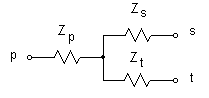
The impedances are related by the following formulas.
 (Eq. 8a)
 (Eq. 8b)
 (Eq. 8c)
 (Eq. 8d)
 (Eq. 8e)
 (Eq. 8f)
In the equations, all impedances must be referred to a common voltage. Note that Xst and Rst are measured at the secondary voltage. If all impedances are to be at the primary voltage, Xst and Rst must be transferred.
Cables
The minimum data needed for cables is size, length, voltage rating, and type. Size, voltage rating, and type of cables is embossed into the jacket. Size and type of aerial cable may be shown on a drawing or listed on an invoice. Lengths may be measured, determined from mine maps, or paced off and estimated. Some cables such as types SHD and MPF have different constructions for different voltage ratings and the voltage rating will need to be specified. It will be embossed in the cable jacket. It should be noted if more than one cable is used in parallel. The spacing of conductors of aerial cable will affect inductance. The computer program uses a default spacing of three feet. If the spacing is different than three feet, it should be noted. The computer program has stored values for resistance and reactance per thousand feet for most commonly used cable types. This data is also available in cable standards and manufacturer’s specifications. Resistance is specified at ambient temperature.
Cable operating temperature has an effect on the resistance of a cable. Most cables have a rated operating temperature of 90 °C. Aerial cable is rated 75 °C. If different operating temperature ratings are specified, they should be noted. The computer program uses fully loaded cables at their rated operating temperature to calculate minimum available currents. The cables have higher resistances at their rated operating temperature ratings than at ambient temperature. The resistance at rated operating temperature can be calculated from the resistance at ambient temperature using the following formula.
 (Eq. 9)
Where: R2 = resistance at operating temperature
R1 = resistance at ambient temperature
T2 = rated operating temperature
T1 = ambient temperature
α = temperature coefficient of resistivity corresponding to temperature T1 (0.00393 for copper at 20 °C)
When calculating maximum available current by hand, the resistance of the cable at ambient temperature should be used. However, the current that causes the cable to reach its highest temperature may not be the maximum available current. If the cable is initially at a temperature between ambient and its rated operating temperature and a short-circuit occurs, it is possible that the cable will reach a higher final temperature at a current lower than the maximum available current. The current depends on the cable’s resistance, but the resistance depends on the current. Therefore, the computer program calculates current that causes maximum temperature with an initial temperature of ambient and with an initial temperature at one degree increments up to the cable’s rated operating temperature. This is one place where the power of the computer really comes in handy. The computer program also uses the subtransient reactance (discussed below) to calculate temperature after one cycle of short-circuit. This temperature is used as the initial temperature along with transient reactance in an additional calculation to calculate temperature at the end of the short-circuit (when the circuit protective device opens). The maximum available current calculated in the computer program is actually the current that causes maximum temperature.
Reactance of most cables is published by the manufacturer. The reactance in ohms per 1000 feet of aerial cables with one foot spacing can be found with the following formula.
 (Eq. 10)
GMR is the geometric mean radius in feet. It can be calculated by multiplying the wire O.D. in inches by .03245.
 (Eq. 11)
Where: R = wire radius in feet
D = wire diameter in feet
d = wire diameter in inches
The reactance of aerial cable depends on the spacing between wires. Reactance at spacings other than one foot can be calculated with the following formula.
 (Eq. 12)
Motors
Motors are a source of short-circuit current. They will act like generators when a short-circuit occurs. At a minimum, motors must be specified by horsepower which will be listed on the motor nameplate. Their reactance may also be specified. Motors have two values of reactance, subtransient and transient. Subtransient reactance is the reactance of the motor during the first cycle of the short-circuit. Transient reactance is the reactance of the motor during the remainder of the short-circuit. The computer program supplies typical values of subtransient and transient reactance for motors. Resistance is considered to be negligible. AC motors may be further identified as induction or synchronous. Synchronous motors can be 6-pole or 8- to 14-pole. The subtransient and transient reactance will vary depending on whether the motor is induction, 6-pole synchronous, or 8- to 14-pole synchronous. It also varies between induction motors rated less than or equal to 600 volts and induction motors rated greater than 600 volts. Induction motors will not contribute to a short-circuit after the first cycle. Typical values of reactance are listed in Table 11.
| Type of Motor | Subtransient Reactance (per unit) | Transient Reactance (per unit) |
| DC | 0.15 | 0.30 |
| 6-pole Synchronous | 0.15 | 0.23 |
| 8- to 14-pole Synchronous | 0.20 | 0.30 |
| Induction ≤600 Volts | 0.25 | - |
| Induction >600 Volts | 0.17 | - |
Table 1
Subtransient and transient reactances are usually given in per unit values. The actual value of reactance can be found with the following formula.
 (Eq. 13)
Where: XPU = per unit reactance
V = voltage
HP = horsepower
Subtransient reactance should be used to calculate maximum available short-circuit current. Minimum available short-circuit current does not usually include contributions from motors, but when it does, transient reactance should be used in the calculation. A&CC does not include motor contribution in minimum available short-circuit current. When adding impedances working down through a circuit, the impedance of a motor should be added in parallel with the total impedance up to the point in the circuit where the motor contributes. This reduces the impedance at that point. Adding impedances in parallel is most easily done by first converting resistance and reactance to conductance and susceptance, adding the conductances and susceptances, and converting the conductance and susceptance back to resistance and reactance. Conductance, susceptance, resistance, and reactance are related by the following formulas.
 (Eq. 14a)
  (Eq. 14b)
 (Eq. 14c)
  (Eq.14d)
Where: R = resistance
X = reactance
G = conductance
B = susceptance
Generators
Generators are treated just like motors. They are specified by kVA, subtransient reactance, and transient reactance. The kVA will be listed on the generator nameplate. Table 2 lists typical values of reactance for dc and four types of ac generators2. The four types are two-pole turbine, four-pole turbine, salient pole with dampers and salient pole without dampers.
| Type of Generator | Subtransient Reactance (per unit) | Transient Reactance (per unit) |
| DC | 0.15 | 0.30 |
| 2-Pole Turbine | 0.09 | 0.15 |
| 4-Pole Turbine | 0.14 | 0.23 |
| Salient Pole with Dampers | 0.20 | 0.30 |
| Salient Pole without Dampers | 0.30 | 0.30 |
Table 2
Reactance is calculated with the following formula.
 (Eq. 15)
Where: XPU = per unit reactance
V = voltage
kVA = kilovolt-ampere rating
Capacitors
Capacitors are specified by kVAR on their nameplates. This is kVA reactive. If no tolerance is specified, 15% may be used. Capacitors will feed a short-circuit just like motors and generators. The following formula calculates reactance for a capacitor using a tolerance of 15%.
 (Eq. 16)
Where: V = voltage
kVAR = kilovolt-amperes reactive
Rectifiers
Efficiency is the only rating needed for rectifiers. If no efficiency rating is specified, 99% can be assumed. Current through the rectifier is reduced by the factor Efficiency (%) / 100.
Minimum Available Current
Minimum available current is calculated for a line to line arcing fault using the following formula.
 (Eq. 17)
Where: VLL = line to line voltage
ZMAX = maximum impedance
This formula is used for AC and the DC output from a three phase rectifier. The factor of 0.95 accounts for voltage fluctuations. The maximum impedance is calculated from the maximum resistances and reactances for all the elements in the circuit. For AC circuits, the current is further reduced by multiplying by an arcing fault factor, KA. This factor is listed in Table 3 for various voltages3.
-
Voltage (V)
KA
V ≤ 480
0.85
480 < V ≤ 600
0.90
600 < V ≤ 1040
0.95
1040 < V
1.0
Table 3
For DC circuits the arc voltage depends on the current. First, the current is calculated with Equation 17. If the calculated current is greater than or equal to 600 amperes, the arc voltage is 60 volts. If the calculated current is less than 600 amperes, the arc voltage is calculated with the following formula4.
 (Eq. 18)
Where: I = initially calculated current
The voltage is then reduced by the arc voltage and the available current is recalculated.
Maximum Available Current
Maximum available current for AC circuits is calculated for a three-phase bolted fault using the following equation.
 (Eq. 19)
Where: VLL = line to line voltage
ZMIN = minimum impedance
Maximum available current for DC circuits is calculated for a line to line bolted fault using the following equation.
 (Eq. 20)
Where: VLL = line to line voltage
ZMIN = minimum impedance
Example
A mine is supplied 95 MVA of power at 34.5 kV with an X/R ratio of 5.23. The power travels 1200 feet through number 2, ACSR aerial cable with three-foot spacing to a substation. The substation has a secondary voltage of 12.47 kV and is rated 10 MVA with 6.08% impedance. The power then travels 6000 feet through number 2/0, 15 kV, mine power feeder cable to an underground power center. The power center has a secondary voltage of 1040 volts and is rated 1350 kVA with 5.0% impedance. Power then travels 850 feet through number 2/0, 2 kV, shielded trailing cable to a continuous miner. If a short-circuit occurs on the continuous miner at the point where the trailing cable ends, what are the minimum and maximum available short-circuit currents?
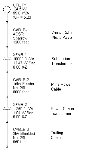
Figure 1
1. Starting at the utility, calculate the impedance using equation 4. Remember to use the voltage at the short-circuit, 1040 volts.
From the impedance and X/R ratio, find X and R.

2. Now, find the reactance and minimum and maximum resistance for the aerial cable. The GMR must first be found with Equation 11. From manufacturer’s specifications, the O.D. of number 2, ACSR wire is 0.316 inch.

The reactance is then found with Equation 10.
Since this is the impedance for one-foot spacing, you must correct for three-foot spacing using Equation 12.
The reactance of 1000 feet of number 2, ACSR aerial cable is 0.1304Ω. The reactance for 1200 feet is 1.2 * 0.1304 = 0.1565Ω. This needs to be converted from the overhead line voltage to the voltage at the short-circuit.

From the manufacturer’s specifications, the resistance of number 2, ACSR aerial cable is 1.753 Ω per mile at 75 °C. The resistance of 1200 feet is 0.3984 Ω at 75 °C. Multiplying by the ratio of the voltages squared gives a maximum resistance of 0.0004 Ω. To get the minimum resistance, the resistance at 75°C must be converted to the resistance at 20 °C using Equation 9.
3. The next component in the system is the substation. First, find the impedance using Equation 7.
The X/R ratio is not specified for the substation. A value of 4.9 can be assumed. Using this value and the impedance, find X and R.

4. Next is the 6000 feet of number 2/0, 15 kV, mine power feeder cable. From manufacturer’s specifications, reactance of 1000 feet of this cable is 0.038 Ω. The reactance of 6000 feet at 1040 volts is calculated as follows:

From manufacturer’s specifications, resistance of this cable at 20°C is 0.0792 Ω per 1000 feet. Resistance of 6000 feet at 1040 volts would be:
The maximum resistance will be at 90 °C, the rated operating temperature of mine power feeder cable.

5. The power center is the next component in the circuit. First find the impedance.
The X/R ratio is not specified for the substation. A value of 4.9 can be assumed. Using this value and the impedance, find X and R.

6. Last is the 850 feet of number 2/0, 2 kV, shielded cable. From manufacturer’s specifications, reactance of 1000 feet of this cable is 0.031 Ω. The reactance of 850 feet is 0.85 * 0.031 = 0.0264 Ω. From manufacturer’s specifications, resistance of this cable at 20°C is 0.0839 Ω per 1000 feet. The minimum resistance (RMIN) of 850 feet is 0.85 * 0.0839 = 0.0713 Ω. The maximum resistance is the resistance at the 90 °C rated operating temperature of mine power feeder cable.

7. Now that all the resistances and reactances are calculated, we total them and calculate impedances and available currents.
| Component | Minimum Resistance (Ω) | Maximum Resistance (Ω) | Reactance (Ω) |
| Utility | 0.0021 | 0.0021 | 0.0112 |
| Aerial Cable | 0.0003 | 0.0004 | 0.0001 |
| Substation | 0.0013 | 0.0013 | 0.0065 |
| Mine Power Feeder Cable | 0.0033 | 0.0042 | 0.0016 |
| Power Center | 0.0080 | 0.0080 | 0.0393 |
| Trailing Cable | 0.0713 | 0.0909 | 0.0264 |
| Total | 0.0863 | 0.1069 | 0.0851 |
Table 4


 Amperes
 Amperes
Conclusion
Accurate calculations of available short-circuit currents can be made without a power systems specialization in electrical engineering. Symmetrical components and the per-unit system can be left for more advanced analyses. Hand calculations can still be tedious though. A computer program can make short work of the calculations.
References
- Recommended Practice for Electric Power Distribution for Industrial Plants, Std. 141-1976, IEEE, 1976.
- Electrical Transmission and Distribution Reference Book, East Pittsburgh, PA, Westinghouse Electric Corporation, 1964.
- William S. Vilcheck, George Fesak, and William J. Helfrich, “Instantaneous Circuit Breaker Settings for the Short-Circuit Protection of Three-Phase 480-, 600-, and 1040-V Trailing Cables,” IEEE Transactions on Industry Applications Volume IE-17 No. 4, pp. 362-368, IEEE, July/August, 1981.
- George Fesak, William S. Vilcheck, William J. Helfrich, and David C. Deutsch, “Instantaneous Circuit Breaker Settings for the Short-Circuit Protection of Direct Current 300- and 600-V Trailing Cables,” IEEE Transactions on Industry Applications Volume IE-17 No. 4, pp. 369-375, IEEE, July/August, 1981.